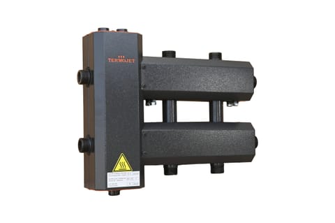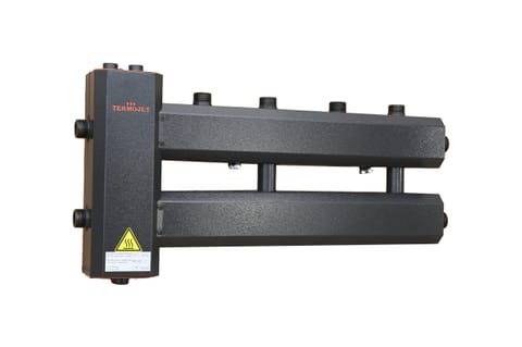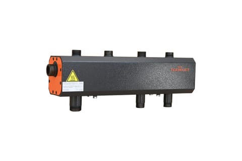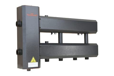

Manifold Termojet in thermal insulation 4+1 down MHS42D125(200)
Manifold with hydraulic separator KGS42N.125(200) — a Termojet "2-in-1" unit for 4+1 circuits with downward outlets : a distribution manifold combined with the hydraulic separator GS-26 in a single bo…
per unit · payment on delivery or by invoice
Technical specifications
Description
Manifold with hydraulic separator KGS42N.125(200) — a Termojet "2-in-1" unit for 4+1 circuits with downward outlets: a distribution manifold combined with the hydraulic separator GS-26 in a single body. This arrangement simplifies installation and saves free space in the boiler room, with a capacity of up to 60 kW at ΔT=10 °C and 95 kW at ΔT=20 °C.
The unit operates as follows: the built-in hydraulic separator creates a low pressure-loss zone between the primary boiler circuit and the secondary consumer circuits — the pumps do not "steal" flow from each other, the boiler operates stably. The manifold section distributes the heat transfer fluid to circuits with 1″ outlets and a centre-to-centre spacing of 125 mm. The built-in air separator vents microbubbles to the air vent (connection G ½″), and the sludge trap settles dirt, which is drained through a valve G ½″.
Scenarios: boiler rooms with four to five circuits — underfloor heating, floor-by-floor radiators, DHW boiler, ventilation; systems with solid-fuel boilers; heat pump piping where separation and distribution are needed simultaneously — see Termojet heat pumps. Downward outlets are convenient when circuit pipe runs pass below the manifold. Pump groups from the Termojet pump group catalogue are installed on the circuits.
Advantages of KGS from Termojet:
- one unit instead of a hydraulic separator and manifold — fewer connections, less space, and less installation time;
- air and sludge separation — protection of the boiler, pumps, and valves;
- 125 mm standard and brackets included — fast installation;
- Ukrainian manufacturing: manufacturer's price, availability, warranty.
Technical specifications: number of outlets — 4+1 (downward), capacity 60 kW at ΔT=10 °C and 95 kW at ΔT=20 °C, maximum flow rate Gmax 6.35 m³/h, boiler connection — 1¼″, heating circuit connection — 1″, centre-to-centre spacing — 125 mm.
Smaller configuration with downward outlets — KGS22N.125(200) for 2+1 circuits; a separate hydraulic separator GS-26 1¼″ — if the separation and distribution need to be placed apart. All versions — in the catalogue of Termojet manifolds with hydraulic separator.
Frequently Asked Questions
Is a separate hydraulic separator needed for this manifold?
No, the hydraulic separator GS-26 is already built into the body — the unit simultaneously separates the circuits hydraulically and distributes the heat transfer fluid.
What is connected to the G ½″ outlets?
On top — an automatic air vent for releasing air, on the bottom — a drain valve for periodic sludge removal.
Product reviews
No reviews for this product yet. Be the first!
Related Products